Published On Apr 27, 2022
NOTE: There's an error in the graphs where i label 20.1W as the max power on a data point below 20W. This was because i accidently clipped the Y-axis at 20W, but the maximum power was in fact 20.1W
This is the second part of my video on building a 3d printed compressed air turbine, which you can find here:
• 3d Printed Compressed Air Turbine
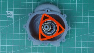
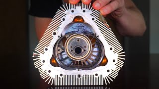
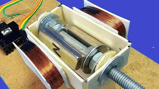
In this video I'll be experimenting to find the best rotor and casing geometry for a 2D-flow turbine. I'm focusing on 2D flow because of the relative ease of machining parts, since I eventually plan to build one of these out of aluminum or brass to power with steam.
All the tests are conducted at 50 PSI with a 1/16" nozzle.
Another goal of this project is to see if it's feasible to use a 3d-printed turbine for Brayton cycle refrigeration (like the ACM on an airliner does). This requires extracting energy from the compressed air in the form of mechanical work to drop its temperature, so a more efficient turbine will have more cooling power (and provide more mechanical output to drive auxiliary devices like a secondary compressor).
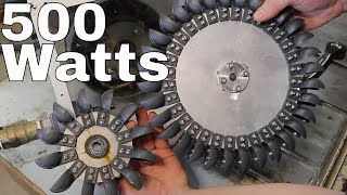
Overall, my best configuration achieved a ~20% improvement over my last video, but there's a relatively large amount of scatter in my data, probably due to vibration and temperature dependance. Some further improvements I still haven't looked at are:
-Tighter tolerances between the turbine rotor and casing
-A convergent/divergent nozzle to convert more of the pressure energy to kinetic energy
-Better seals to prevent pressure leakage between stages (or to the outside).
Music Used:
Kevin MacLeod - Groove Groove